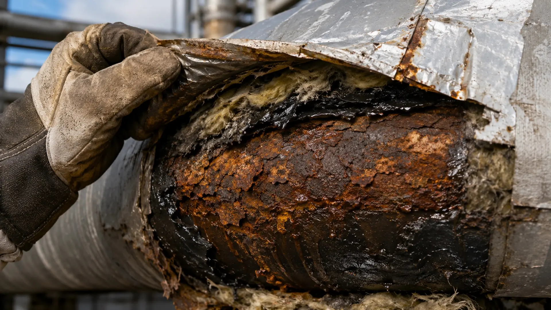
Key takeaways
- 01A dead leg corrodes at a rate unrelated to the flowing pipe next to it, so it needs its own corrosion rate, its own CMLs, and usually its own circuit.
- 02API 570 sets a recommended injection point circuit from at least twelve inches or three pipe diameters upstream to the second change in direction downstream, or twenty-five feet past the first, whichever is less.
- 03The best control for a dead leg that serves no purpose is removal, and the record should show the removal decision was considered.
- 04Dead legs and injection points hide because they are not on the drawing or not in the circuit; the register is the control, not the inspection.
A piping circuit is a promise that everything inside it corrodes in roughly the same way. Dead legs and injection points break the promise. The stagnant end of a blanked branch does not see the flow that keeps the main line clean. The two feet downstream of a chemical quill do not see the same fluid as the pipe upstream of it. When both are swept into the parent circuit, the circuit's corrosion rate describes neither, and the interval computed from that rate is a guess dressed as a calculation. This paper covers how a dead leg inspection program is built under API 570: how to find the locations, how to circuit them, where to place CMLs, and what the record has to carry so the forgotten end stays on the schedule.
What is a dead leg and why does API 570 single it out?
API 570 defines dead legs as components of a piping system that normally have no significant flow. The list in the standard is practical rather than theoretical: blanked branches, lines with normally closed block valves, lines with one end blanked, pressurized dummy support legs, stagnant control valve bypass piping, spare pump piping, level bridles, relief valve inlet and outlet header piping, pump trim bypass lines, high point vents, sample points, drains, bleeders, and instrument connections. Any of these can be a dead leg. Most units have hundreds.
The standard singles them out because the corrosion mechanism changes at the stagnant end. In the flowing pipe, water and solids stay entrained and the wall stays at process temperature. In the dead leg, water drops out and collects, solids settle, dissolved species concentrate, and the metal temperature drifts toward ambient. Underdeposit corrosion, microbiologically influenced corrosion, and acid dewpoint attack all start where the live line never sees them. In some services the dead leg also traps the chemistry that a downstream injection was meant to neutralize.
API 570 asks the inspector to monitor dead legs where the corrosion rate is known to differ, and it makes the removal point explicit: owner-users should consider removing dead legs that serve no further process purpose. This is worth reading as a record requirement. If the dead leg still exists, the record should show that removal was considered and why it was not done.
How does API 570 define an injection point circuit?
Injection points are locations where chemicals or process additives enter a stream: corrosion inhibitors, neutralizers, water wash, antifoulants, process chemicals. The concern is localized corrosion where the injected fluid has not yet mixed: concentration at the wall, impingement from the quill, wet spots where water injection meets a hot vapour line.
API 570 recommends treating each injection point as a separate inspection circuit with explicit boundaries. The upstream limit is at least twelve inches or three pipe diameters upstream of the injection point, whichever is greater. The downstream limit is the second change in flow direction past the injection point, or twenty-five feet beyond the first change in flow direction, whichever is less. The circuit can be extended by the owner-user where the process chemistry or mixing behaviour warrants it.
Within the circuit, the standard recommends:
- Thickness measurements at the injection nozzle itself, the pipe wall opposite the nozzle where impingement occurs, and at each change in direction downstream, since elbows and tees concentrate the unmixed stream.
- Radiography or scanning UT for the first inspection, because injection point corrosion is localized and spot readings can miss it. Once the pattern is known, spot UT can follow the pattern.
- A separate interval. Injection point circuits designated as such have an inspection interval that should not exceed three years, with the option of a more frequent interval based on the observed rate.
Two mistakes recur. The first is defining the circuit around the quill only and missing the downstream elbow where the wall actually thins. The second is folding the injection circuit into the parent line so the injection point is inspected at the parent's ten-year Class 2 interval.
Where do dead legs and injection points hide?
They hide because the tools used to build the inspection program are not the tools that created them.
- Not on the P&ID. Instrument connections, bleeders, and dummy legs are often drawn as a symbol or not at all. The isometric shows them; the circuit register was built from the P&ID.
- Created after commissioning. A pump is spared, a bypass is added, a temporary chemical injection becomes permanent. The piping changed; the circuit register did not.
- Reclassified by operations. A line that flowed is valved off for a mode change and stays off for years. It is now a dead leg and nobody told inspection.
- Injection points on the wrong drawing. Chemical injection skids are vendor packages. The tie-in exists on the vendor drawing, not on the owner's isometric.
- Insulated and out of sight. A dead leg under insulation in a service that cycles through the corrosion under insulation temperature range hides two mechanisms at once.
Finding them is a walkdown exercise, not a desk exercise. The inspector walks the circuit with the isometric, marks every branch that terminates or is normally closed, every injection tie-in, and every low point where a normally closed line could collect water. Each one gets an identity in the register before anyone decides how often to inspect it. The register is the control. Inspection only works on what the register knows.
How should dead legs be circuited and CMLs placed?
The circuit decision is whether a dead leg needs its own corrosion rate. If the rate is plausibly different from the parent, and for stagnant ends it usually is, the dead leg needs its own CMLs and its own rate, whether or not it is drawn as a separate circuit. Many programs keep the dead leg inside the parent circuit for class and interval purposes but tag its CMLs so the rate is computed on the dead leg alone. Either approach works if the record is explicit.
CML placement follows the mechanism:
- The stagnant end. The blank, the closed valve, the cap. This is where water and solids collect.
- The bottom of horizontal dead legs. The six o'clock position, where water sits.
- The interface with the live line. The tee or branch connection, where turbulence and temperature transition meet.
- Low points and traps in vertical dead legs, and the point where a vertical leg turns horizontal.
- For injection points, the nozzle, the wall opposite the nozzle, and each downstream change of direction inside the circuit.
Each CML should carry the same fields as any other: nominal thickness, minimum required thickness and how it was set, material, diameter and schedule, and the reading history. Small-bore dead legs usually govern on a structural minimum rather than a pressure calculation, and the record should say which.
What should the dead leg record carry?
A dead leg program is only as good as its register. The register needs, for each location:
- Identity and location. Circuit, line number, isometric reference, and a description an inspector can find from the ground.
- Classification. Dead leg or injection point, and the type (spare pump line, level bridle, chemical injection, water wash).
- Justification. Why it exists, and the removal decision with its reasoning if it was retained.
- Damage mechanisms expected. Underdeposit, MIC, dewpoint, erosion at the quill. The mechanism drives the technique and the CML placement.
- CML set with placement rationale and the readings history.
- Corrosion rate computed on the dead leg's own readings, with the short-term and long-term rates both visible.
- Interval and next due date, and the class of the parent circuit.
- Change history. When the location was added, when it was reclassified, when a CML was added or retired, and by whom.
The last item is the one most programs lack. A dead leg that was on the register in 2015 and is missing in 2024 either was removed from the plant or was removed from the register. The record has to distinguish the two.
Where do dead leg programs fail in practice?
- The parent rate is applied. The dead leg inherits the parent circuit's corrosion rate, remaining life is computed against a rate the dead leg never experienced, and the interval extends to ten years.
- The register is a spreadsheet. One tab per unit, updated by whoever remembers. Locations added in the field never make it to the tab.
- Injection circuits are too short. The circuit ends at the first elbow and the second elbow is where the wall fails.
- The technique does not match the mechanism. Spot UT on a location where corrosion is pitting, so the reading is taken on the wall between pits.
- Turnaround findings do not close the loop. A dead leg is found corroded, repaired, and the repair is filed under the work order rather than against the CML. The corrosion rate never learns.
- Removal is never considered. The dead leg is inspected forever because nobody owns the question of whether it is needed.
Each of these is a records failure. The engineering is well understood; the difficulty is keeping several hundred locations on a schedule across decades and staff turnover.
How intelliSPEC handles it
intelliINSPECT and intelliINTEGRITY put dead legs and injection points on the same footing as every other inspection location, with their own history.
- Locations with identity. The asset hierarchy is a graph of nodes with roles from company down to asset, component, and weld. A dead leg or injection point is a component node with its own CMLs, its own history, and its own place under the line, so it cannot disappear when a circuit is redrawn.
- CMLs that carry the inputs. Each CML point carries 64 fields, including nominal thickness, tMin and the method that set it, material, diameter and schedule, grid geometry, and three corrosion rates (short-term, long-term, and maximum). The governing rate is the maximum, and remaining life is computed from it against tMin.
- Interval capped at half life. The API 570 interval calculator caps the interval at half the remaining life computed from the location's own rate, so a stagnant end cannot inherit a ten-year interval from the flowing pipe beside it.
- Damage mechanisms as records. Thinning and cracking mechanisms are first-class records that attach to the location, so the expected mechanism, the technique, and the CML placement are stored together rather than in a note.
- Findings on drawings. Drawing and PDF annotation with automatic CML point detection lets an inspector mark the stagnant end on the isometric in the field, and the mark becomes a CML rather than a photo of a pen mark.
- A change history that survives. The hash-chained audit trail records who added, reclassified, or retired a location and when, and audit events are never auto-deleted. A location that leaves the register leaves a trace.
- Offline in the unit. The register, drawings, and prior readings are on the device with full offline capture, so the walkdown happens where the dead legs are, not at a desk afterwards.
For the terms used here, see the glossary. For how the program fits a refinery or a pipeline terminal, see oil and gas and pipelines and terminals.