Key takeaways
- 01API 571 catalogs the damage mechanisms that affect fixed equipment in refining and describes each by its affected materials, critical factors, morphology, prevention and inspection methods.
- 02A damage mechanism review assigns mechanisms to each circuit and component from process conditions and materials, and the assignment is the input that API 510, API 570 and API 580 all require before a plan or a risk number is meaningful.
- 03The mechanism selects the NDE method: general thinning wants thickness measurement, local thinning wants scanning or profile radiography, cracking wants surface and shear wave methods, and HTHA wants advanced ultrasonic techniques.
- 04intelliSPEC holds damage mechanisms as first-class records attached to the component, feeds them into RBI scoring and the CUI wizard family, and lets Spectra answer questions about the mechanism record with a citation to the source.
An inspection program that does not know what it is looking for will measure thickness everywhere and find cracks nowhere. API 571 is the antidote. It is a catalog of the ways refinery equipment fails, organized so an engineer can start from a material, a fluid and a temperature and arrive at the mechanisms that are credible, the places they will appear, and the methods that will find them. Used properly, it is not a reference book but the first step of a strategy: assign the mechanisms, then let the mechanisms choose the locations, the methods, the intervals and the operating limits. This paper describes that strategy and what the record must carry so that the assignment made in a review room survives into the field.
What is API 571 and how is it organized?
API RP 571, Damage Mechanisms Affecting Fixed Equipment in the Refining Industry, describes each mechanism under a consistent set of headings.
- Description of damage. What is physically happening to the metal.
- Affected materials. Which alloys are susceptible and which resist.
- Critical factors. The variables that control whether and how fast the mechanism proceeds: temperature, concentration, velocity, stress, hardness, water content and others.
- Affected units or equipment. Where in a refinery the mechanism is found.
- Appearance or morphology. What it looks like, which is what tells the inspector which method can see it.
- Prevention and mitigation. Materials, process controls, coatings, heat treatment.
- Inspection and monitoring. The methods that detect and size it.
- Related mechanisms.
The current edition groups mechanisms into general categories (mechanical and metallurgical failure, uniform and localized loss of thickness, high-temperature corrosion, environment-assisted cracking) and adds process-unit-specific material, including process flow diagrams that place the mechanisms on the unit. The organizing insight is the critical factors section. Every mechanism has a small number of variables that drive it, and those variables are what a review asks the process engineer to supply.
The companion practices complete the picture. API RP 970 covers corrosion control documents, which record the mechanism assignments and the controls for a unit. API RP 584 covers integrity operating windows, the process limits derived from those mechanisms. API RP 941 carries the Nelson curves for high-temperature hydrogen attack. API 580 and 581 consume the mechanism assignments as the basis for damage factors.
How does a damage mechanism review feed the inspection plan?
A damage mechanism review (DMR) is a facilitated, multidisciplinary study: a materials or corrosion engineer, a process engineer, an inspection lead and an operations representative walk the unit circuit by circuit. For each circuit or piece of equipment they establish the material of construction, the normal and excursion operating conditions, the stream composition including contaminants, and the operating history, then work through the credible mechanisms and record the result.
The output is the assignment: for each circuit and component, the mechanisms that apply, the critical factors that govern them at this location, the expected morphology and location of damage, and the recommended inspection method and monitoring. That assignment is not a report to file. It is the input three other things require.
- API 510 and API 570 inspection plans require that the damage mechanisms expected for each vessel and circuit be identified and that the inspection methods, extent and locations be chosen to find them.
- API 580 and 581 RBI compute damage factors per mechanism, so a component with no mechanism assigned has no meaningful probability of failure.
- Integrity operating windows are defined per mechanism, so the review is where the windows come from.
The DMR is also the place where circuitization is tested. If two parts of the same line have different assigned mechanisms, they are two circuits. If a circuit has a mechanism that only occurs above a temperature reached in a single exchanger outlet, the CMLs belong there. The review is what turns a piping isometric into a set of places to look.
Which mechanisms drive the most inspection effort?
A handful of API 571 mechanisms account for most of a refinery's inspection scope, and each carries critical factors that a record should hold as structured values rather than narrative.
- Sulfidation. High-temperature sulfidic corrosion of carbon and low-alloy steel, generally above about 500 degrees F (260 degrees C), with rate rising with temperature and sulfur content and worsened in low-silicon carbon steel. Found in crude, vacuum, coker, FCC and hydroprocessing units. General thinning, detected by thickness measurement, with attention to low-silicon components identified by PMI.
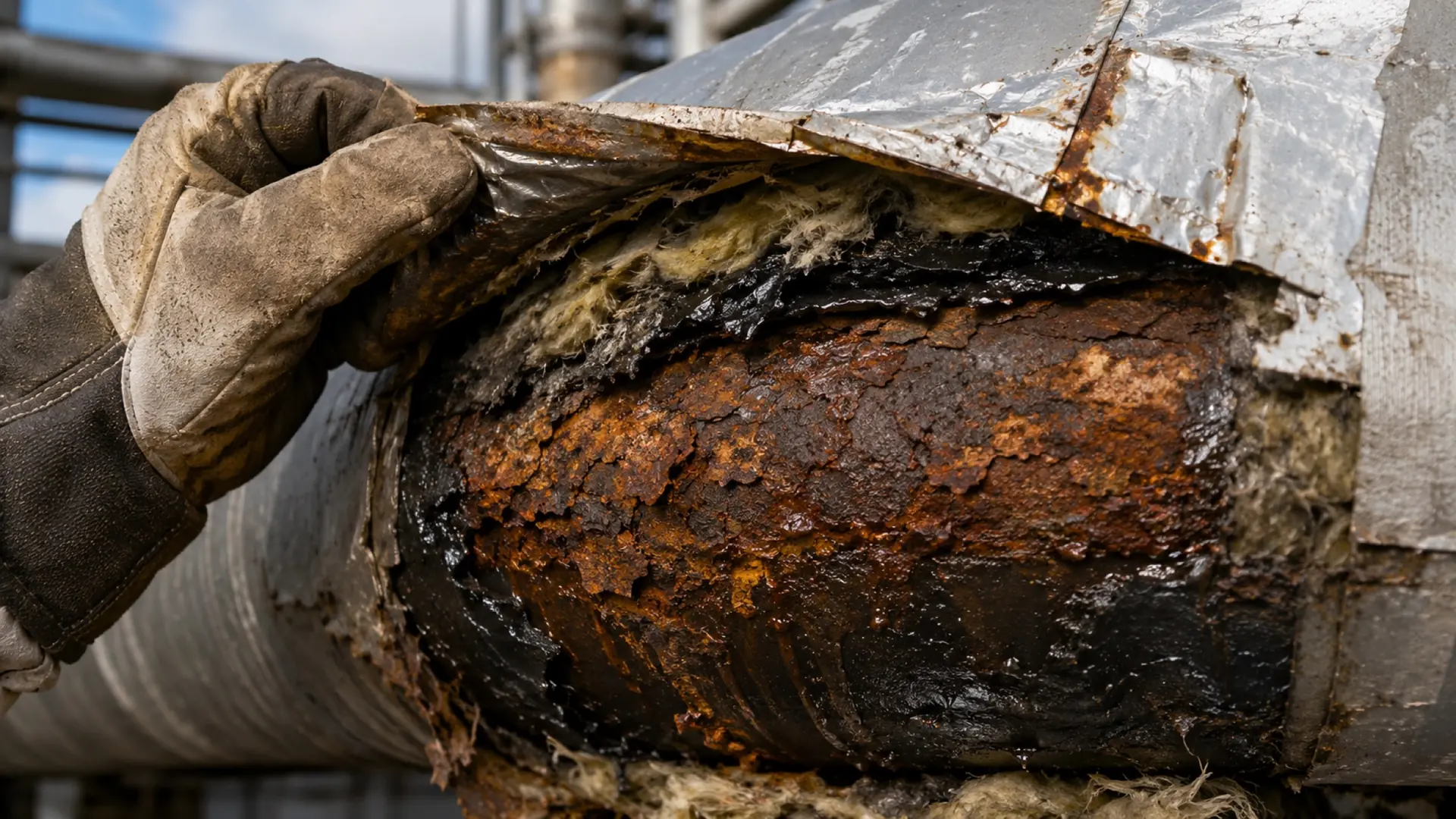
- Corrosion under insulation. Carbon steel between about 10 and 350 degrees F, austenitic stainless (as chloride cracking) between about 140 and 400 degrees F, worst in cyclic and intermittent service and where jacketing is breached. Localized thinning under insulation, found by insulation removal, profile radiography, pulsed eddy current and guided wave screening.
- Wet hydrogen sulfide damage. Blistering, hydrogen-induced cracking, stress-oriented hydrogen-induced cracking and sulfide stress cracking in carbon steel exposed to water with dissolved H2S. Found in sour water, amine, FCC light ends and hydroprocessing effluent. Detected by wet fluorescent magnetic particle testing on internal surfaces, with shear wave and TOFD ultrasonics for subsurface cracking.
- Chloride stress corrosion cracking. Austenitic stainless under tensile stress with chlorides and water, accelerated above about 140 degrees F. Branched transgranular cracking, found by dye penetrant, eddy current and ultrasonics.
- High-temperature hydrogen attack. Carbon and low-alloy steel in hydrogen service above the material's Nelson curve in API RP 941. Methane formation at grain boundaries leads to fissuring and eventual cracking. Detected by advanced ultrasonic methods including backscatter, velocity ratio, TOFD and phased array, with emphasis on non-post-weld-heat-treated carbon steel welds.
- Naphthenic acid corrosion. Crude and vacuum units processing high-acid crudes, roughly above a total acid number of 0.5, at temperatures from about 425 to 750 degrees F, driven by velocity and turbulence. Localized thinning at elbows, pump impellers and transfer lines, found by scanning ultrasonics and profile radiography.
- Creep. Time-dependent deformation above a material-dependent temperature, roughly 700 degrees F for carbon steel, in heater tubes, hot piping and reactors. Found by dimensional measurement, replication, hardness and knowledge of time at temperature.
- Erosion and erosion-corrosion. Velocity, solids and impingement geometry. Localized thinning at direction changes and downstream of restrictions.
The pattern across the list is that each mechanism has a temperature band, a chemistry, a material susceptibility and a morphology. Those four facts are what the record needs against each component, and they are what changes when the process changes.
How do integrity operating windows connect to API 571?
An integrity operating window is a limit on a process variable, set so that the assigned damage mechanisms stay within the rates the inspection plan assumed. API RP 584 defines three kinds: critical limits that require immediate action, standard limits that require action in a defined time, and informational limits that trigger a review. Each window traces to a mechanism from the DMR.
Examples make the connection concrete. A sulfidation window is a maximum temperature on a stream with a known sulfur content. A CUI window may be a temperature range that a normally hot line must not fall into for extended periods. An ammonium bisulfide window is a maximum concentration and a maximum velocity in a hydroprocessing effluent air cooler. A chloride cracking window is a maximum chloride level and a temperature ceiling for a stainless system.
For the record, the important property is the link. When an excursion occurs, the inspection organization should be able to ask which equipment carries the mechanism that window protects, and answer from the data rather than from the memory of whoever ran the review. That means the window, the mechanism and the component are three records tied together, not three spreadsheets.
How should damage mechanisms be recorded against equipment?
The DMR spends its value if its output lives in a slide deck. A working record has these properties.
- Structured, per component. Each assignment is a record with a mechanism identifier from API 571, the component or circuit it applies to, the critical factor values at this location (temperature range, concentration, velocity, material), the expected location and morphology, and the recommended inspection method.
- Dated and attributed. When the review was held, who participated, and what process basis was assumed.
- Versioned. When a feed change or MOC alters the basis, the assignment changes and the prior assignment remains visible with its date.
- Consumed downstream. The inspection plan cites the assignment for each CML and method. The RBI damage factor cites it. The operating window cites it.
- Reviewable. The next DMR starts from the record, compares it with what inspection actually found, and corrects the assignment where the mechanism did not appear or a different one did.
The last property is the feedback loop that makes the strategy improve. If wet H2S cracking was assigned to a drum and three internal inspections with WFMT found none, the assignment can be downgraded with evidence. If CUI was not assigned to a line and it appeared, the review missed a factor, and the record shows exactly what was assumed.
How does the mechanism select the NDE method?
The inspection and monitoring heading of each API 571 entry is a method selection guide, and the logic reduces to morphology and location.
- Uniform thinning (sulfidation, CO2 corrosion, general atmospheric corrosion): ultrasonic thickness at CMLs, with profile radiography on small bore. Rate trending is the goal.
- Localized thinning (naphthenic acid, erosion, under-deposit, CUI, ammonium chloride): spot readings miss it. Scanning ultrasonics, phased array, profile radiography, and for CUI, insulation removal or screening by pulsed eddy current and guided wave before removal.
- Surface-breaking cracking (chloride SCC, amine SCC, caustic cracking, polythionic acid SCC, sulfide stress cracking): wet fluorescent magnetic particle on ferritic steel, dye penetrant and eddy current on stainless, after surface preparation.
- Subsurface cracking and hydrogen damage (HIC, SOHIC, HTHA): shear wave ultrasonics, time of flight diffraction, phased array, and for HTHA the specialized backscatter and velocity methods.
- Metallurgical degradation (creep, temper embrittlement, sigma phase, graphitization): field replication, hardness, dimensional measurement, and sampling where warranted.
- Blistering and laminations: visual inspection internally and straight beam ultrasonics.
The consequence for the program is that the method is decided before the outage, from the assignment, and the record of the inspection must state which mechanism it was looking for. An inspection recorded as "UT thickness, no findings" on a vessel whose assigned mechanism is wet H2S cracking is not evidence about that mechanism. That distinction is exactly what API 581 inspection effectiveness grading depends on.
How intelliSPEC handles it
intelliSPEC holds damage mechanisms as first-class records, with thinning and cracking mechanisms attached to the component in the asset graph rather than typed into a report. Because the platform is metadata-driven, with entity definitions and forms configured through the form designer rather than code, the critical factor fields a site wants on each assignment, temperature band, chemistry, velocity, material susceptibility, are configured fields with history, and the assignment carries the reviewers and date with it.
The assignments flow downstream inside the platform. In intelliINTEGRITY, semi-quantitative API 580 and 581 scoring reads probability and consequence against the component and its mechanisms, and the corrosion summary and API 510 and 570 interval draw on the CML history in intelliNDT, where each CML holds tMin and its method, material and three corrosion rates. For the mechanism that generates the most field effort, the CUI wizard family in intelliINSPECT carries the work through visual survey, suspect area identification, insulation removal, ultrasonic and advanced NDE, repair, recoat, inspection test plan and frequency assessment, so each step is a record bound to the location and to the mechanism that sent the crew there. Inspections record the method used, with photos and video bound to the component at capture, which is what an effectiveness grade later needs to see.
Where the corrosion control document, the last review minutes and the inspection history live in the tenant's own records, Spectra retrieves across them and answers with a citation to the source record and collection, so the question "which circuits on this unit carry a sulfidation assignment above 550 degrees" is answered from the record, not from recollection. Every change to an assignment carries actor, tenant and request id and is written to a hash-chained audit trail that a verify routine can recompute.
API 571 tells you how equipment fails. The strategy is recording that knowledge where the equipment is, so every inspection that follows knows what it is looking for.